Series, Parallel, or Bypass? What two centrifugal pumps reveal in real-time simulation
Est. Reading: 5 minutes
Series, Parallel, or Bypass? What two centrifugal pumps reveal in real-time simulation 3
Two identical centrifugal pumps and one question that every engineering student can answer. Connect them in series and the heads add. Connect them in parallel and the flows add. Both statements are true, and neither is what usually decides whether an installation performs.
What decides it is the pipework around them — and a bench rig makes that argument in about ten minutes, in a way that a lecture cannot.
The Rule, and What It Is Worth
Start with one pump at full speed and both throttle valves wide open. The rig settles at 1.65 L/s against a total head of 8.06 m. Close the discharge valve completely and the flow goes to zero at 9.68 m, which is the shutoff head. That is the entire pump characteristic in two numbers.
Now bring in the second pump in true series at the same speed. The head goes to about 16.1 m and the flow rises by roughly six percent, to 1.75 L/s. The heads added, as advertised; the flow barely moved, because the characteristic is almost flat over that stretch and the extra head only walks the operating point a little way along the system curve [1][3].
Switch to parallel at the same throttle setting and the mirror image happens: the flows add and the head stays where the single pump had it. So far, textbook.
The Valve That Cancels a Pump
Two pumps are in series only if the piping puts them in series. On this rig, valve V-IN2 admits fluid to the second pump — and in the series line-up it doubles as a bypass around the first one.
Leave V-IN2 open in series, which is an easy thing to do here and an easier thing to do on a real installation, and the second pump’s suction is equalized with the system suction pressure. The first pump’s head is short-circuited. The system now sees one pump’s head, about 8.06 m instead of 16.1, with both machines running.
The first pump has not stopped. It is still turning at 1800 rpm and still drawing power: with no flow passing through it, its no-load demand alone is 110 W. Two motors, two motor bills, one pump’s worth of head. Close the valve at steady state and watch the head double on the trend in front of you.
The opposite mistake is worse, and just as easy. Stop the first pump while the two are in true series and it is no longer a pump, it is a restriction in the line. Flow collapses to zero and the second pump dead-heads at its shutoff head. That is exactly why a series pair is piped with a bypass in the first place — and exactly why the discipline is that the bypass is shut whenever both pumps are running. The rig lets you be wrong in both directions inside the same five minutes, which is the cheapest way to learn it [2][4].
The Arrangement Is a Property of the System
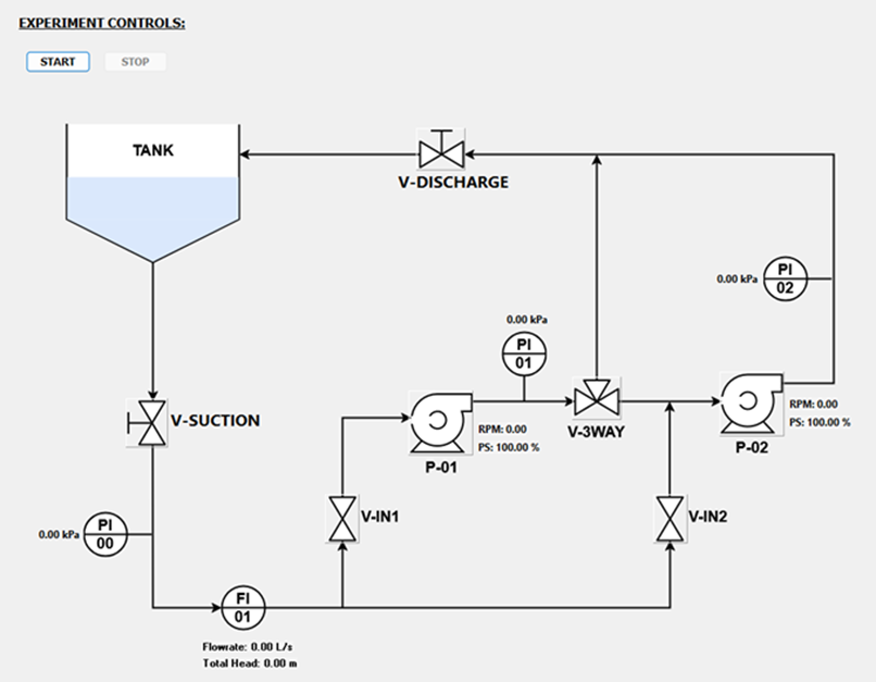
Double the head and double the flow are what the pumps can offer. What arrives depends on what they are pushing against, and on this rig the two throttle valves are the system curve, laid out in front of you and yours to move, as shown in Figure 1.
The standard exercise is to close the discharge valve from fully open to fully shut in ten percent steps, hold steady state at each one, and record flow and head. Repeat the same sweep in parallel, in series, and with a single pump in service, then overlay the three. The question “series or parallel” stops being a rule to memorize and becomes a crossing point you can see: where resistance climbs steeply with flow, pressure is what you are short of and series wins; where the system barely resists, added pressure is wasted and added flow is not [1][5].
One practical detail reproduces the physical unit and catches people out every time. The effective restriction is set by whichever of the two valves is more nearly closed. Leave the suction valve partly shut while recording a characteristic curve on the discharge valve and the results are quietly limited by the wrong valve over part of the range.
Series, Parallel, or Bypass? What two centrifugal pumps reveal in real-time simulation 4
Figure 1. PiPump process diagram — the two pumps, the three-way connection valve between them, the two isolation valves and the suction and discharge throttle valves that set the system curve.
Speed Instead of Throttling
Each pump has its own independent speed setting, so an unbalanced pair is available — which is what real plants run far more often than the matched textbook case. The affinity laws apply throughout: flow varies with speed, head with the square of speed, shaft power with the cube. Halve the speed setting and the flow halves, the head falls to a quarter, and the shaft power falls to an eighth [1][5].
At the reference point the simulator reports 130 W of hydraulic power against 189 W of mechanical power, a pump efficiency of about 69 percent and 1.0 Nm of motor torque. Drop the speed to half and the mechanical power falls to around 24 W. Throttling to the same flow instead leaves the motor near full power and burns the difference across the valve. Written down, that is an energy argument. Recorded from two runs you did yourself, it is a measurement [6].
What Comes Out of a Run
Capture Snapshot writes the current operating point to its own file, one row per capture, so a throttle sweep plots straight out as a pump curve with no filtering or averaging in between. The continuous log runs alongside it and carries the derived quantities too: per-pump head, inlet and outlet velocities, hydraulic and mechanical power, motor torque and both pump and overall efficiency.
That last column is worth a session on its own. Plot overall efficiency against flow rate across a full throttle sweep and the best efficiency point is somewhere on the line you drew — to be found, rather than quoted from a datasheet.
Conclusion
Students get to settle series against parallel on evidence instead of a rule. Instructors get a fluid machinery experiment a whole cohort can run without queueing for one test rig, repeatable enough to build a report around. Engineers get a safe place to find out what a spare pump actually buys, and what a bypass left open actually costs, before that judgment has to be made on a live system.
To request a demonstration of PiPump and the full PiControl laboratory simulator portfolio, contact info@PiControlSolutions.com or visit www.picontrolsolutions.com.
References
[1] Karassik, I.J., Messina, J.P., Cooper, P., and Heald, C.C. (Eds.), Pump Handbook, 4th ed., McGraw-Hill, New York, 2008.
[2] Hydraulic Institute, ANSI/HI 9.6.3 Rotodynamic Pumps — Guideline for Operating Regions, Hydraulic Institute, Parsippany, 2017.
[3] McCabe, W.L., Smith, J.C., and Harriott, P., Unit Operations of Chemical Engineering, 7th ed., McGraw-Hill, New York, 2005, Chapter 8: Transportation and Metering of Fluids.
[4] Perry, R.H. and Green, D.W. (Eds.), Perry’s Chemical Engineers’ Handbook, 9th ed., McGraw-Hill, New York, 2019, Section 10: Transport and Storage of Fluids.
[5] White, F.M., Fluid Mechanics, 7th ed., McGraw-Hill, New York, 2011, Chapter 11: Turbomachinery.
[6] U.S. Department of Energy, Improving Pumping System Performance: A Sourcebook for Industry, 2nd ed., DOE/GO-102006-2079, Washington, 2006.