Two Geometries, Two Flow Directions, One Temperature Cross: A Benchtop Heat Exchanger, Simulated in Real Time
Est. Reading: 4 minutes
Put this to a room of engineering students. Hot water goes into a heat exchanger at 50 °C. Cold water goes in at 22 °C. At the far end, which one comes out warmer?
“The hot one, obviously.” Nine times out of ten.
It is wrong. Reverse the flow direction, slow both streams down, and the cold water walks out warmer than the hot water does. Not warmer than it went in — warmer than the hot stream’s own outlet. The first time an engineer sees that on a panel, the instinct is to go hunting for a swapped thermocouple.
There isn’t one. That is simply what counter-current flow does.
Why the Direction of Flow Decides It
Send both streams in at the same end, and they chase each other toward the same temperature. The cold one climbs, the hot one falls, the gap narrows — and that is as far as it goes. They can never trade places, however long you build the exchanger. Parallel flow has a ceiling baked into it.
Send them in at opposite ends and the whole arrangement changes. The hot stream keeps meeting fresh cold water the entire way down, so it goes on giving up heat right to the exit. The cold stream enters where the hot fluid is at its hottest and keeps climbing. Nothing stands between the two lines and a crossing — and with enough surface area and slow enough flow, they cross [1][2].
Every heat transfer textbook says so. Watching it happen on a live instrument panel is a different kind of knowing.
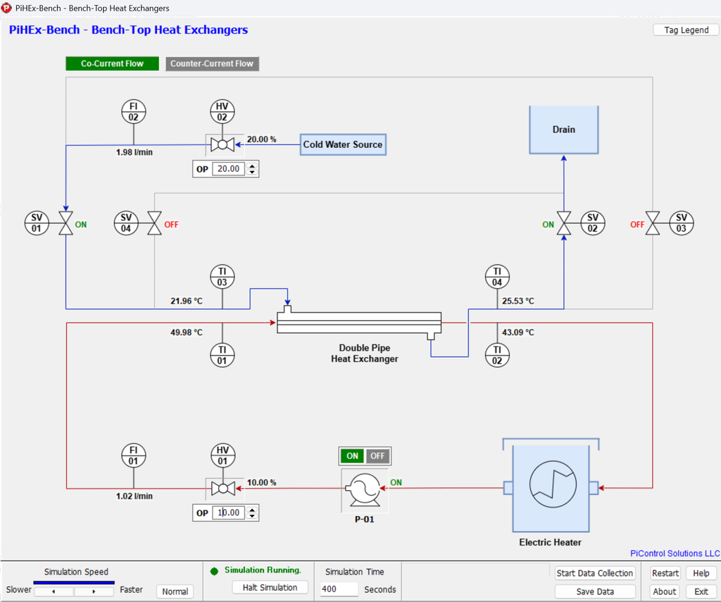
Figure 1. PiHEx-Bench main process diagram – live instrument readings, the flow configuration selector, and temperature and flow trends.
Two Valves and a Button
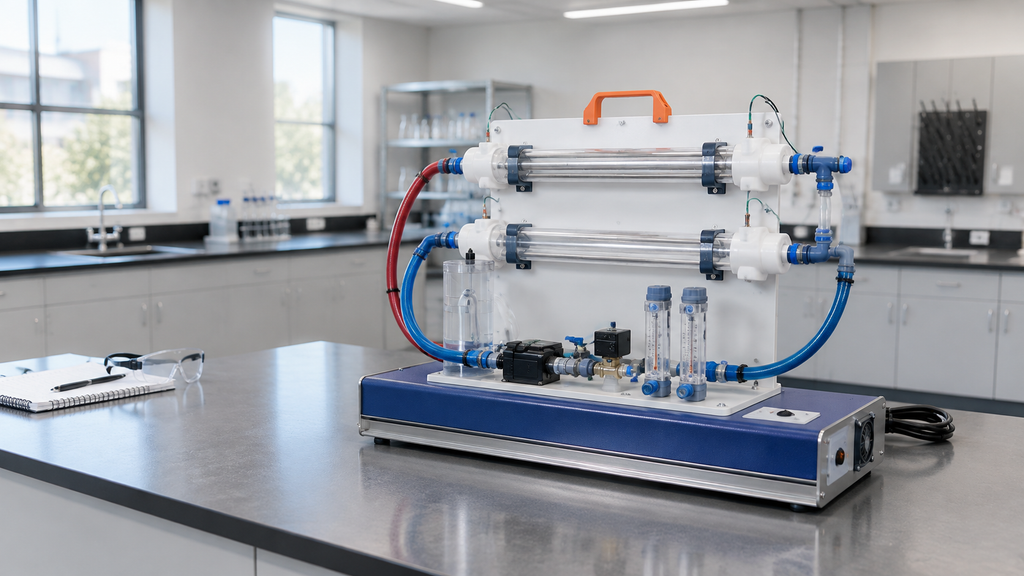
PiHEx-Bench is a real-time simulator of the bench-top heat exchanger service unit that sits in unit operations laboratories everywhere [6]. The exchanger is chosen on the startup screen — a double-pipe or a shell-and-tube — along with its tube diameter, length, count, and overall heat transfer coefficient. Whichever you pick is the one piped up in front of you for that session. Flow direction is set on the process diagram itself, with the valves still shut.
At ordinary laboratory flow rates you will not see the crossing, and that is the exercise rather than a shortcoming. Run the double-pipe exchanger at a litre a minute per side and the hot stream leaves around 43 °C, the cold around 29 °C. A comfortable, unremarkable gap.
Now turn both valves down. Not up. Slow the streams to roughly a third of a litre a minute and give the exchanger time to work on them. The two outlet traces drift together, touch, and swap places: the hot stream settles near 35.6 °C, the cold one near 36.2 °C.
Then take the run back to its initial state, select co-current, and dial the same two flows back in. Same exchanger, same flow rates, same inlet temperatures — and this time the machine refuses. The traces close on each other and stall, and no amount of waiting moves them past. That contrast is the entire lesson, and it costs about five minutes.
The Bigger-Looking Exchanger Is Not the Better One
Restart with the other geometry, and it makes an argument of its own — not the one most people expect. The shell-and-tube unit looks like the serious piece of equipment: a bundle of seven tubes inside a shell, the shape of the things that run refineries. It even carries slightly more heat transfer area than the plain double-pipe.
It is still the weaker of the two here. Its heat transfer coefficient is lower, and area and coefficient together determine how much of the available heat an exchanger can actually capture. Run each in turn at the same flow rates, and the double-pipe takes more heat out of the hot stream. Walk each toward the crossing point, and the shell-and-tube has to be slowed further still before its outlets will swap over [3][4].
Which is the part a specification sheet will never teach: more surface area is not the same thing as a better exchanger.
What You Get to Experiment With
Two exchanger geometries and both flow directions — eight documented runs, each one set up from the startup screen.
Real dynamics. Flows take time to arrive, and temperatures ease into place; every reading carries instrument noise, and you judge steady state rather than the software announcing it.
Geometry under your control. Tube diameter, length and count, and the overall heat transfer coefficient are all entered before the run — so how hard the exchanger works is yours to change.
Every run exports to a timestamped CSV file.
The Numbers Are Yours to Work Out
That CSV holds measurements, not conclusions. Valve positions, pump state, both flow rates and all four temperatures, with the exchanger type and its full geometry written into the header. What it does not contain is a single finished result — no heat duty, no log-mean temperature difference, no overall coefficient, no effectiveness.
Those are the work, and they are exactly what the lab report asks for [1][5]. The case study puts the question directly: can the cold outlet in counter-current flow exceed the hot outlet, and under what conditions? It stops being a thought experiment the moment you can turn two valves down and watch it happen [6].
Conclusion
Students come away with an intuition no formula on its own delivers. Instructors get eight ready-made runs and a case study to hang them on. Engineers get somewhere risk-free to sanity-check a configuration before committing to it.
McCabe, W.L., Smith, J.C., and Harriott, P., Unit Operations of Chemical Engineering, 7th ed., McGraw-Hill, New York, 2005, Chapter 15: Heat-Transfer Equipment.↩︎
Incropera, F.P., DeWitt, D.P., Bergman, T.L., and Lavine, A.S., Fundamentals of Heat and Mass Transfer, 7th ed., John Wiley & Sons, Hoboken, 2011, Chapter 11: Heat Exchangers.↩︎
Kays, W.M. and London, A.L., Compact Heat Exchangers, 3rd ed., McGraw-Hill, New York, 1984↩︎
Kern, D.Q., Process Heat Transfer, McGraw-Hill, New York, 1950. (Classical reference for double-pipe and shell-and-tube exchanger design.↩︎
Standards of the Tubular Exchanger Manufacturers Association (TEMA), 10th ed., Tubular Exchanger Manufacturers Association, Tarrytown, 2019.↩︎
Perry, R.H. and Green, D.W. (Eds.), Perry’s Chemical Engineers’ Handbook, 9th ed., McGraw-Hill, New York, 2019, Section 11: Heat-Transfer Equipment.↩︎